
Access Networks
The user can configure the following three types of networks supported.
Connected Networks
Managed Connected Networks (Traditional VLANs)
Managed Routed Networks
Adding New Connected Network
To configure the connected network, perform the following steps.
Steps
Click Next on the Interfaces page or click Access Networks. The Access Networks page appears, see below.
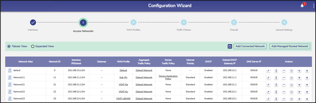
Access Networks
Initially, the Default network is available. The user can configure multiple networks. Once, the networks are configured, the networks become available on the Access Networks page. This section has two view, Tabular View, and Expanded View. The default view is Tabular View. Click Expanded View to see the details of the networks in expanded form, see below.
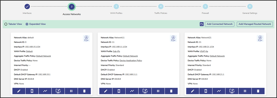
Expanded View
To add a Connected Access Network, perform the following steps.
Steps
Click Add Connected Network button present on the top right of the screen. The Add Connected Network page appears, see below.
By default, Connected Networks are unmanaged, i.e., ‘Managed Connected Network?’ is set to ‘No’. See Figure Add Connected Network. To create a Managed Connected Network, set ‘Managed Connected Network?’ to Yes. See Figure Add Managed Connected Network.
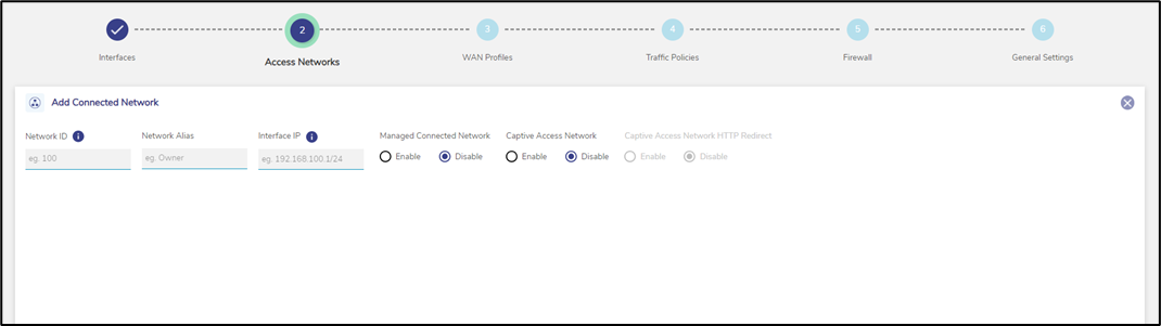
Add Connected Network
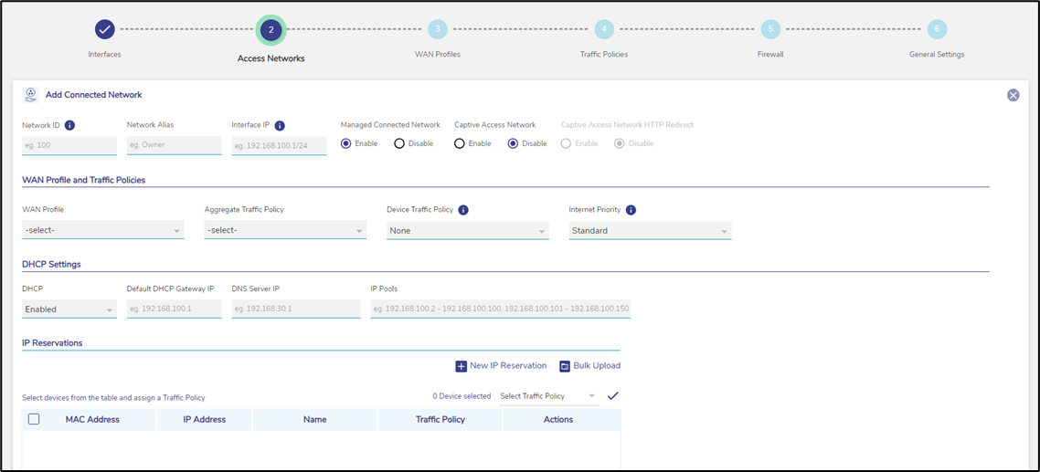
Add Managed Connected Network
Note: The user can configure multiple local networks to be used based on the hierarchy. They can configure the local network for the crew of the site, a local network for the captain of the site, and a local network for the owner of the site distinctly.
To enter data in the respective fields, see table below.
Fields | Description |
Network ID | Enter a unique numeric ID from 2 to 4090. For details about the network ID, click i icon next to the network ID. Network ID is known as a VLAN ID. Once the network ID is configured, user cannot modify or update the VLAN ID or network ID in the future. |
Network Alias | Enter a unique alias of the network. |
Interface IP | Enter an interface IP address and subnet mask. |
Managed Connected Network | Click one of the following options.
The Managed Connected Network is the traditional VLANs’. |
Captive Access Network | Captive Portal allows for each crew member/client to have a provisioned account with an associated Service Plan. The Account’s “service plan” is customized to match corporate policy (Quota, Duration, Traffic Policy – e.g., 10GB/month with defined traffic policies). Click one of the following options.
|
WAN Profile and Traffic Policies | |
WAN Profile | Select a WAN Profile. A single WAN Profile, I.e., Default Profile will be created in the system after the EdgeOS System installation, and this profile will be assigned by default to any newly created Access Network. However, user can configure the distinct WAN profiles and assign to the Network. For details about configuring the WAN profiles, see section WAN Profiles. |
Aggregate Traffic Policy | Select a Network Traffic Policy. A single Traffic Policy, I.e., Default Network will be created in the system after the EdgeOS System installation, and this policy will be assigned by default to any newly created Access Network. However, user can configure the distinct policies and assign to the Network. For details about configuring the network traffic policies, see section Traffic Policies. |
Device Traffic Policy | Select a Device Traffic Policy. Initially, on Network creation, no Device Traffic Policy is assigned to the network. However, user can configure the distinct device traffic policy and assign to the network. For details about configuring the device traffic policies, see section Device Traffic Policies. The user can assign the traffic policy to a device from also General Settings. For details, see General Settings. However, the traffic policy assigned to a device from this step will override the traffic policy of that device. 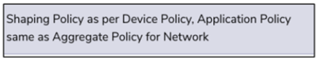 Shaping Policy |
VPN | Select a configured VPN. |
|
|
Internet Priority | Select an Internet Priority. For details, click i next to the Internet Priority, see below. 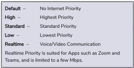 Internet Priority |
DHCP Settings | |
DHCP | To enable DHCP so that a DHCP can automatically assign the IP address and the other allied configuration details to a host on a network to communicate with the endpoints, click Enable. |
Default DHCP Gateway IP | The default IP address becomes available. User can assign a new IP address. For this, click and delete the IP address and then assign a new IP address. |
DNS Server IP | The default IP address becomes available. User can assign a new IP address. For this, click and delete the IP address and then assign a new IP address. They can assign a maximum of three DNS IP addresses. |
To configure the DNS proxy, perform the following steps. Steps
By default, the status Not In Use is displayed. | |
To remove the DNS proxy, perform the following steps. Steps
Or,
The status Not in Use is displayed, see Figure Configure DNS Policy (Not in Use). | |
IP Pools | The default sequential range of the IP addresses becomes available. User can assign a new range of the sequential IP address. For this, click and delete the IP address range and then assign a new sequential range of the IP address. User can assign multiple sequential IP address range excluding the specific IP addresses of that range. This is an example. 192.168.10.2-192.168.10.100, 192.168.10.151-192.168.10.200, 192.168.10.220- 192.168.10.254 The following IP addresses will not be assigned to the device in the network.
DHCP will assign the IP address to a device on the specified network based on the IP address range. |
IP Reservations | |
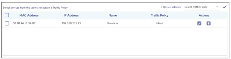
New IP Reservation | To reserve an IP address for a device, perform the following steps. Steps
Configure the MAC Address, IP Address, Name, Traffic Policy, and Actions fields. |
MAC Address - Enter the MAC address of a device. | |
IP Address - Enter IP address from the sequential IP address range specified in the IP Pools field. | |
Name - Enter a name for the device. | |
Traffic Policy - Click a traffic policy to be assigned to the device. Inherit indicates that the device will inherit the device policy of the network. | |
Actions - To save the IP reservation configuration, click Green tick icon. or, To cancel the IP reservation configuration, click x. | |
Bulk Upload | To upload details of the IP reservation, perform the following steps. Steps
|
To download the bulk IP reservation template, click Download Reservations. The IP reservation template downloads in CSV format, see Figure IP Reservations Template in CSV Format. Fill in the required details in the file. For an example, see Figure Example of IP Reservations Template in CSV Format. The first row is referred to as the header row. Save the file.
| |
User can modify the details of the IP reservation. To modify the details of the IP reservation, perform the following steps. Steps
Details of the IP reservation are modified. | |
To delete the details of the IP reservation, perform the following steps. Steps
| |
Table Connected Network Information
Configure Managed Connected Network
Network Updated Successfully
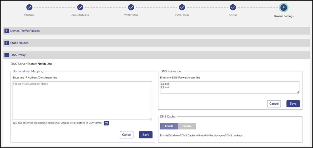
Configure DNS Policy (Not in Use)
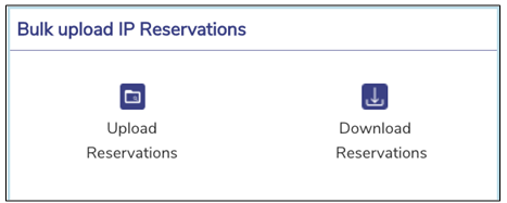
Bulk Upload
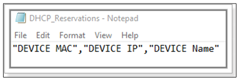
IP Reservations Template in CSV Format
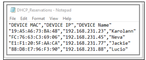
Example of IP Reservations Template in CSV Format
IP Reservations Details
Adding a Managed Routed Network
To add a Managed Routed Network, perform the following steps.
Steps
The pre-requisite to add a Managed Routed Network is to first create an Unmanaged
Connected Network.
Click the Add Managed Routed Network button. The Add Managed Routed Network page appears, see figure below.
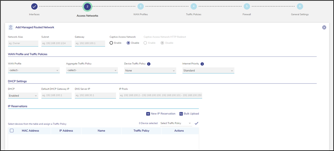
Add Managed Routed Network
To enter data in the respective fields, see table below.
Fields | Description |
Network Alias | Enter a unique alias of the network. |
Subnet | Enter the subnet based on the interface IP address and mask that was configured while configuring the connected network. |
Gateway | Enter the IP address of the device managing the communication with the external network. User must assign the IP address based on the interface IP address that was configured while configuring the connected network. |
Captive Access Network | Captive Portal allows for each crew member/client to have a provisioned account with an associated Service Plan. The Account’s “service plan” is customized to match corporate policy (Quota, Duration, Traffic Policy – e.g., 10GB/month with defined traffic policies). Click one of the following options. No, Default option if Captive functionality is disabled on the Access Network. Yes. To enable Captive functionality on the Access Network. |
WAN Profile and Traffic Policies | |
Same as corresponding fields in Table Connected Network Information. | |
DHCP Settings | |
Same as corresponding fields in Table Connected Network Information. | |
IP Reservations | |
For details of each section, see Table Connected Network Information. | |
Table Managed Routed Network Information
The Connected Network and associated Managed Routed Networks are grouped and appear in the same background color in the Access Networks table. See example table below.
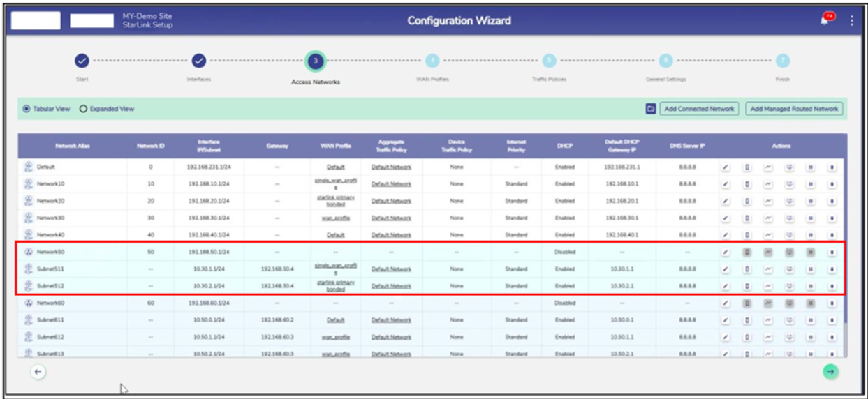
Grouped Networks
Modifying Network
To modify a network, perform the following steps.
Steps
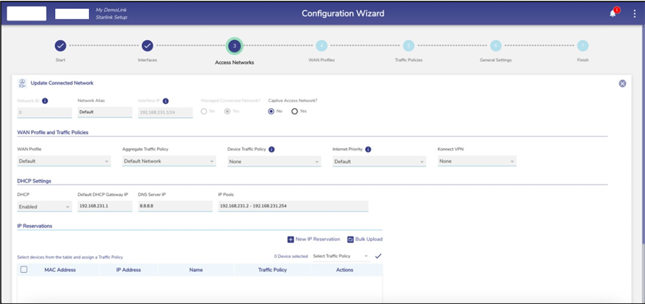
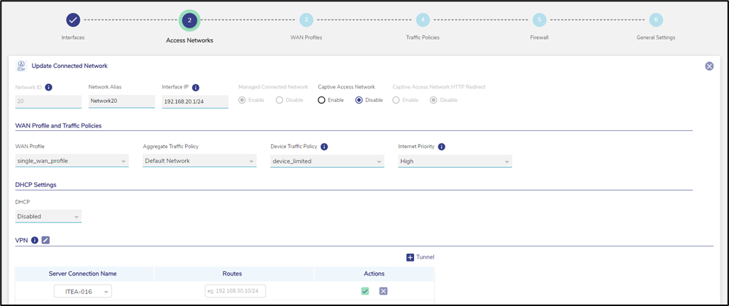
Click pencil icon next to the network under the Action section on the Access Networks page. The Updated Connected Network page appears, see Figure Update Connected Network. To enter data in the respective fields, see Table Connected Network Information.
Note: All fields except Network ID, Interface IP, and Managed Connected Network? are editable.
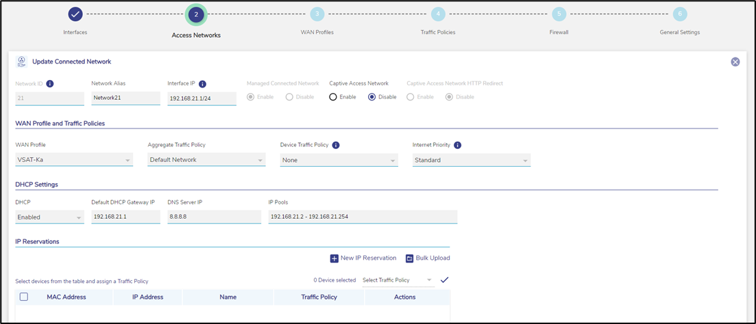
Update Connected Network
Click Save.
Modifying Device Profile
To modify the device profile, perform the following steps.
Steps
Click Device Profile icon next to the network under the Action section on the Access Networks page. The Device Profile page appears, see figure below.
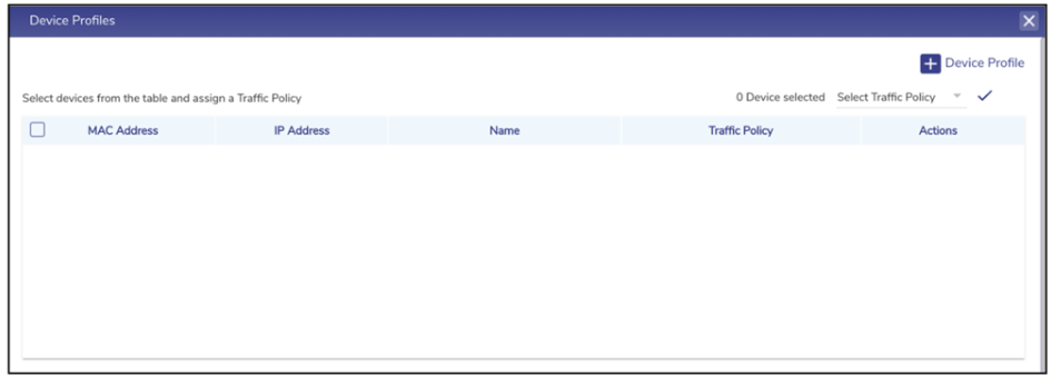
Device Profile
Click Device Profile on top right to add a new device profile.
To enter data in the respective fields, see Table Connected Network Information.
Click Save.
The user cannot modify the device profiles of the connected network.
Viewing Network Usage Data
To view network usage data, perform the following steps.
Steps
Click Network Usage next to the network under the Action section on the Access Networks page. The Network Usage page appears, see figure below.
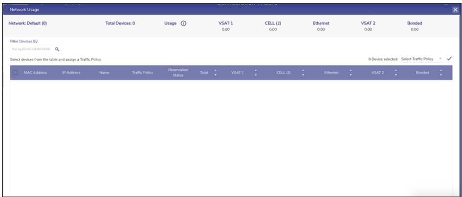
Network Usage
For details about the fields, see table below.
Fields | Description |
Network | This indicates the name of the network |
Total Devices | This indicates the count of the devices connected to the network. |
Usage | This indicates details about the quota of the network. To view the quota details, click i icon . Details about the quota are displayed, see Figure Quota Details. |
VSAT | This indicates the total data consumed by the VSAT. |
VSAT-LEO | This indicates the total data consumed by the Starlink. |
L-BAND | This indicates the total data consumed by the L-Band. |
CELL (LTE) | This indicates the total data consumed by the CELL (LTE). |
Ext5G | This indicates the total data consumed by Ext5G. |
Wi-Fi | This indicates the total data consumed by the Wi-Fi. |
Ethernet | This indicates the total data consumed by the ETHERNET. |
Bonded | This indicates the total data consumed by the Bonded. |
Filter Devices By | Enter the MAC address of the specific device. Details about the device become available. |
MAC Address | This indicates the MAC address of the device connected to the network. To pause the device, click Pause icon . The Pause Device Profile confirmation message pop-up window appears, see Figure Pause Device Confirmation Message. Click Pause. The Resume icon (resume button) becomes available and the row of the device is highlighted by a color. Or, To resume the device, click Resume icon. The Resume Device Profile confirmation message pop-up window appears, see Figure Resume Device Confirmation Message. Click Resume. |
IP Address | This indicates the IP address assigned to the device. |
Name | This indicates the alias name of the device. To modify the alias name, click pencil icon and modify the alias name. |
Traffic Policy | This indicates the traffic policy assigned to the device. To modify the traffic policy, click pencil icon and modify the traffic policy. For details, see section Traffic Policies. To assign the traffic policy to multiple devices, perform the following steps. Steps
To assign the traffic policy to the devices in bulk, perform the following steps. Steps
|
Reservation Status | This indicates that whether the IP address assigned to the device is reserved. To reserve the IP address of the device, select the corresponding check box. Or, To un-reserve the IP address of the device, clear the check box. |
Total | This indicates the sum of the data consumed by the device on the following WAN links.
|
VSAT | This indicates the quantum of the data consumed by the device on the VSAT. |
CELL (LTE) | This indicates the quantum of the data consumed by the device on the CELL (LTE). |
Wi-Fi | This indicates the quantum of the data consumed by the device connected through Wi-Fi. |
Ethernet | This indicates the quantum of the data consumed by the device on the Ethernet. |
Bonded | This indicates the quantum of the data consumed by the device on the Bonded. |
Table Network Usage
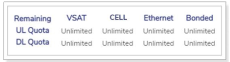
Quota Details
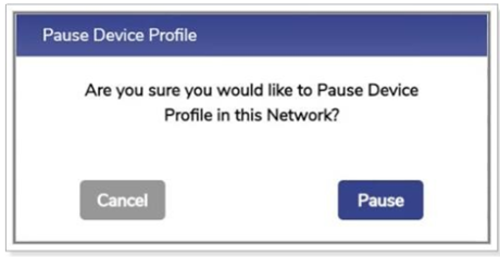
Pause Device Confirmation Message
Resume Device Confirmation Message
Configuring Captive Access Network
Captive Portal allows for each crew member/client to have a provisioned account with an associated Service Plan. The Account’s “service plan” is customized to match corporate policy (Quota, Duration, Traffic Policy – e.g., 10GB/month with defined traffic policies).
To configure an Access Network as Captive, perform the following steps.
Steps
Click icon of the Access Network that the user wants to make Captive.
Set the ‘Captive Access Network?’ field to Yes to enable the Captive Access Network, see Figure Captive Access Network Configuration.
Set the Aggregate Network Policy such that all applications but *.k4mobility.com is denied, see Figure Aggregate Network Policy.
Set the Device Traffic Policy to None.
Click Save. The Captive Access Network will be created. This will show up with Captive Access Network icon next to it, see Figure Captive Access Network.
Create one or more Device Traffic Policies in the Traffic Policy Section which will apply to devices connecting via Captive Access Network, see Figure Device Traffic Policy. These policies will be associated with the plans assigned to users of these devices.
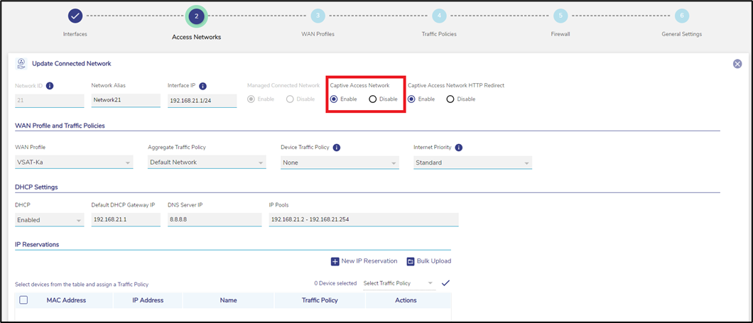
Captive Access Network Configuration
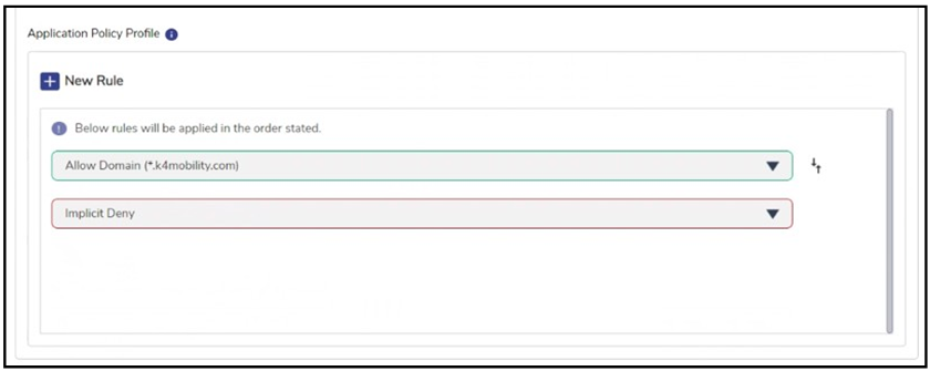
Aggregate Network Policy
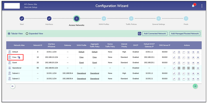
Captive Access Network
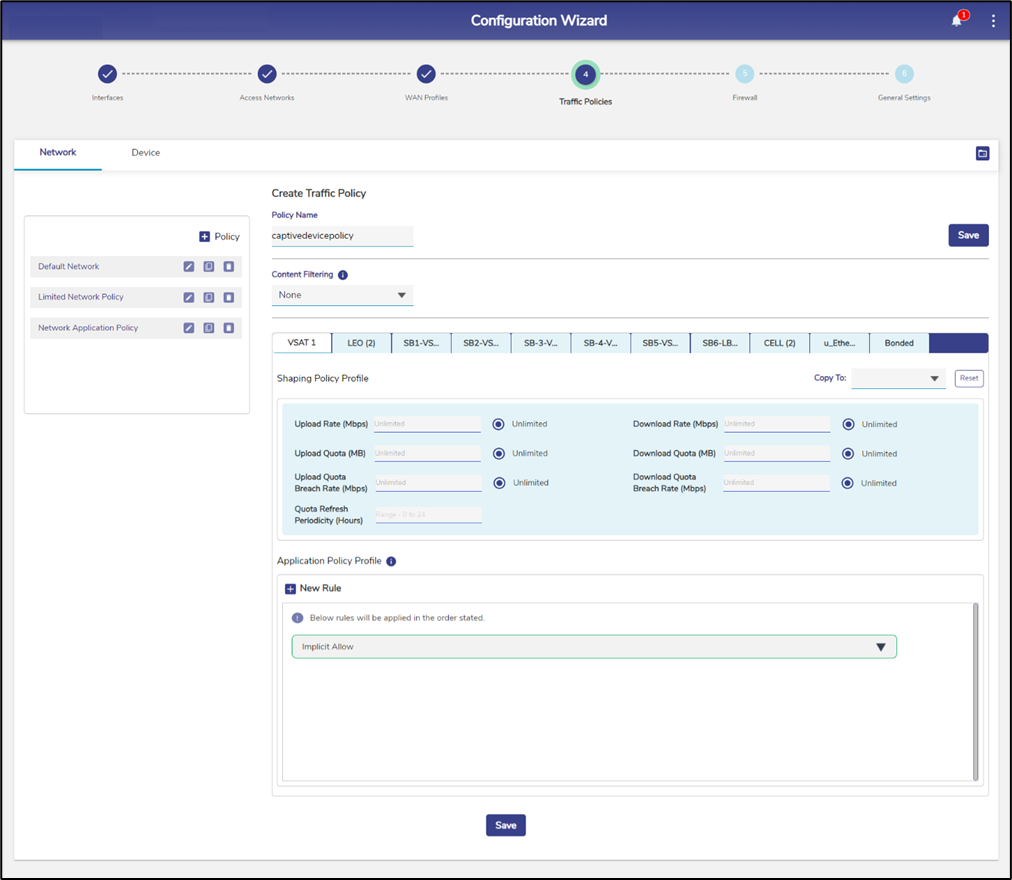
Device Traffic Policy
Configuring VPN
To route the Access Network traffic through the VPN, edit the Access Network configuration to pick the configured VPN end point to route. This allows the EdgeOS System to VPN access networks to a Konnect VPN Server; this is most utilized between EdgeOS Systems. For details of VPN Configuration, see section VPN.
To configure VPN, perform the following steps:
Steps
Click Pencil icon of the Access Network that the user wants to configure VPN for.
In the ‘Access Networks’ configuration for any Connected Network, the server connection to associate with can be selected from the VPN Section. The selection can be done at the time of creating an Access Network or by editing it as shown below.
Scroll down to the VPN section. See Figure VPN Configuration.
Click + Tunnel button to associate any route with any configured VPN connection – route ‘0.0.0.0/0’ is the ‘default’ route. Multiple such routes may be defined – making ‘split tunnel’ configuration possible. Any route not caught by this table will be routed over the default routing of the EdgeServer using the WAN Profile configured.
Choose the VPN Connection from the Server Connection Name dropdown.
Enter the Routes in the CIDR format.
Click the Green tick icon to confirm.
Click X to cancel the operation.
VPN Configuration
LAN Monitoring
To monitor a device connected to the network, perform the following steps.
Steps
Click Computer icon corresponding to the network under the Action section on the Access Networks page. The LAN Monitoring pop-up window appears, see figure below.
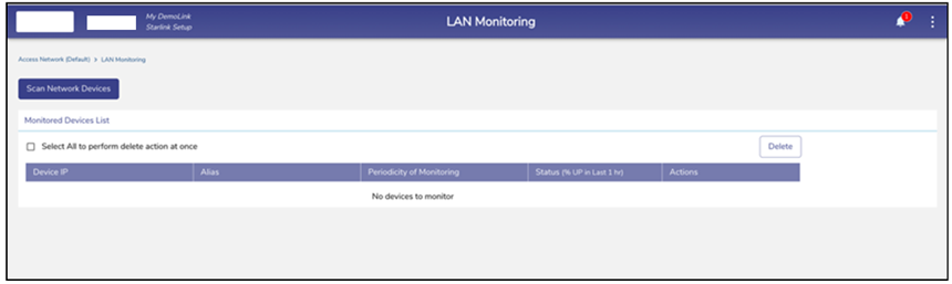
LAN Monitoring
Click Scan Network Devices. The scan is in progress, see figure below.
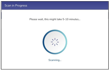
Network Design Scan Progress
The scanned network devices list is displayed, see figure below.
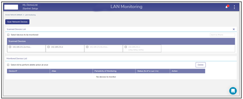
LAN Monitoring
Select the IP address check box of the devices under the Scanned Devices List section. Or,
To select the entire device, select the Select devices to be monitored check box under the Scanned Devices List section.
The IP address of the device becomes available under the Monitored Devices List, see figure below.
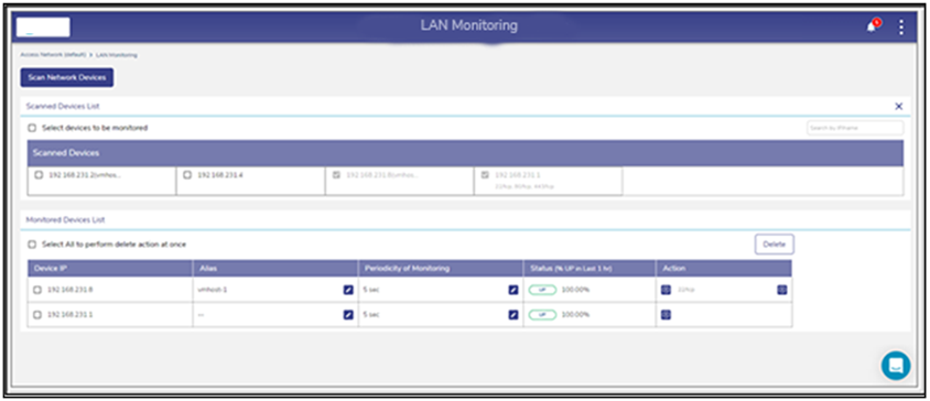
Monitored Devices
If the device is up, then the status Up is displayed under the Status (% UP in Last 1 hr.) section.
If the device is down, then the status Down is displayed under the Status (% UP in Last 1 hr.) section.
Additionally, the duration of the device being up in the last 1 hour is displayed next to the status under the Status (% UP in Last 1 hr.) section.
Configuring Periodicity of Monitoring
To configure the periodicity of monitoring, perform the following steps.
Steps
Click Pencil icon under the Periodicity of Monitoring section on the LAN Monitoring page. The periodicity list becomes available, see figure below.
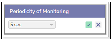
Periodicity of Monitoring
In the periodicity list, click the periodicity.
Click Green tick.
The device is monitored based on the configured periodicity. Or,
To exit without configuring the periodicity of monitoring, click X.
Adding to Konnect
To add to the Konnect, perform the following steps.
Steps
Click Add to Konnect under the Action section on the LAN Monitoring page. The Add to Konnect pop-up window appears, see figure below.
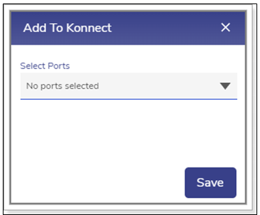
Add to Konnect
Click the port list and then select the port number check box. User can select multiple port numbers.
Click Save. The port numbers are displayed under the Action section, see figure below.
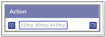
Port Added to the Konnect
In addition to this, the Remove from Konnect icon becomes available under the Action section, see figure below.

Add/Remove from Konnect
Removing from Konnect
To remove from Konnect, perform the following steps.
Steps
Click the Remove from Konnect icon, see Figure Add/Remove from Konnect. The Remove From Konnect pop-up window appears, see Figure Remove from Konnect Pop-up.
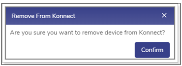
Remove from Konnect Pop-up
Click Confirm.
The device is removed from the Konnect.
Deleting the Monitored Devices
To delete the monitored devices, perform the following steps.
Steps
Select the IP address check box.
User can select multiple devices. Or,
To select all devices, select the Select All to perform delete action at once.
Check box under the Monitored Devices List section.
Click Delete. The Stop Monitoring pop-up window appears, see Figure Stop Monitoring.
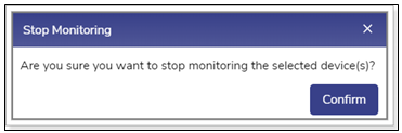
Stop Monitoring
Click Confirm.
The device is deleted. Therefore, it is not monitored.
Pausing or Resuming Network Traffic
To pause the network traffic, perform the following steps.
Steps
Click Pause icon corresponding to the network under the Action section on the Access Networks page. The Pause Network Traffic confirmation message pop-up window appears, see figure below.
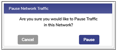
Pause Network Pop-up
Click Pause. The Resume Network Traffic Play button becomes available, and the row of the network is highlighted by color. In addition to this, Pause icon becomes available corresponding to the network under the Network Alias field.
User cannot pause the network traffic of the connected network.
To resume the network traffic, perform the following steps.
Steps
Click Play corresponding to the network under the Action section on the Access Networks page. The Resume Network Traffic confirmation message pop-up window appears, see figure below.
Resume Traffic Pop-up
Click Resume. The network traffic on the network resumes.
Deleting Network
To delete the network, perform the following steps.
Steps
Click Delete icon corresponding to the network under the Action section on the Access Networks page. The Delete Network confirmation message pop- up window appears, see figure below.
Delete Network Pop-up
Click Delete.
The network is successfully deleted. This will impact the DHCP reservations. Therefore, it is highly recommended to verify the network details before deleting the network.