
Updating WAN Trunk
The Interfaces screen allows administrators to configure and manage all network interfaces on the device. This includes LAN, WAN, and Wi‑Fi interfaces, along with their IP addressing, VLAN mapping, link status, and basic properties.
This page is typically used during initial device setup as well as for ongoing network expansion and troubleshooting. The WAN Trunk can also be called as WAN Interfaces. The user can view and update the configuration of the Interfaces present on the KonnectOpen System.
Viewing Configured Interfaces Details
To view details of the Interfaces pre-configured on the KonnectOpen System, do the following steps.
There is a flexibility that any ethernet interface on the KonnectOS System (applicable for all products) can be configured as either WAN interface, LAN interface or for VSAT management. Along with this flexibility, VLANs can be configured on the interfaces and the same can be configured as WAN sub-interface or as LAN access port.
Interfaces are physically labelled on the hardware device as WAN or LAN, but can be configured as either a WAN or LAN port depending on the needed function
-
Login into the KonnectOS Portal.
-
Select the Interfaces option from the side menu bar.
-
The Interfaces tab is selected by default.
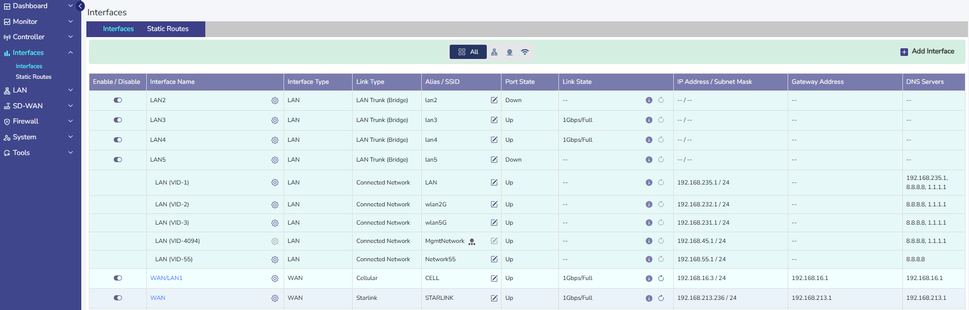
Details of the Interfaces present on the KonnectOpen System are listed on the Interfaces Screen.
Note: By Default, only enabled Interface are shown. To see all the interfaces, click the All Interfaces checkbox on the top. When checked All Interfaces, the user will be able to see all the Interfaces.
The user can also press on the Refresh button to refresh the page and get the latest data. By default, this screen refreshes every 30 seconds.
The user can upload configuration from available backup by clicking on Folder icon.
There are three types of Interfaces i.e., WAN, LAN and VSAT Mgmt. If the Status of an Interface is Up, then the various details such as State of the link, IP address or Subnet Mask populate on the Interfaces Screen. For details of attributes of each row, See tables below.
|
Fields |
Description |
Configuration |
|
Enable/Disable Toggle
|
This slider allows the user to enable or disable this network interface. User can modify an interface only when it is in the disabled state. |
N/A |
|
Fields |
Description |
Configuration |
|
Interface Name |
This indicates the network interface that is available on the site, along with some pre-configuration. User can edit the network interface by disabling it and then clicking on the ‘gear’ icon. |
To edit the interface, perform the following steps. Steps
In this dialog, they can modify: The Interface Type: WAN, LAN or VSAT Mgmt. |
|
|
|
The ‘Alias’, a name for the interface. |
|
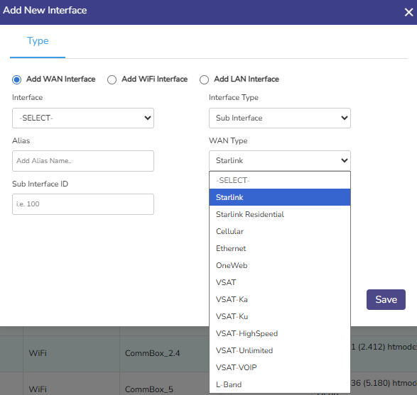
If the Interface Type is ‘WAN’, user can also configure the WAN Type, which is one of:
If Interface Type is ‘LAN’, user can also configure the LAN Type, which is one of:
|
||
|
If the LAN Type is ‘LAN Access’, user must further specify the ‘Sub I/F id’. |
||
|
If Interface Type is VSAT Management, user can also additionally configure:
|
||
|
Virtual IP |
Assign a virtual IP Address to the Interface to hide the given WAN IP. This is useful to manage the redundant IP addresses in the system. |
|
|
No NAT |
Pass the traffic out the WAN Interface without any Source NAT translation. |
|
|
Port Forwarding |
Traffic coming from Source IP (If not specified, traffic from any IP accepted) to port ‘WAN port’, will be forwarded to Natted IP:Natted Port. |
|
|
|
|
|

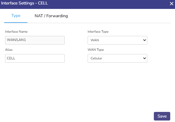
Updating a WAN Interface
To update a WAN Interface, perform the following steps:
-
Click on the Toggle icon and disable the WAN Interface.
-
Click the Gear icon next to the Interface. A popup appears, see Figure Update WAN Interface.
-
Enter the Alias Name.
-
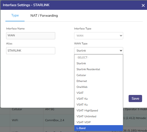
Select the desired WAN type from the drop down, see Figure Select WAN Type.
-
Click Save.
-
Click on the Toggle icon and enable the WAN Interface.
-
The Interface is updated as required.
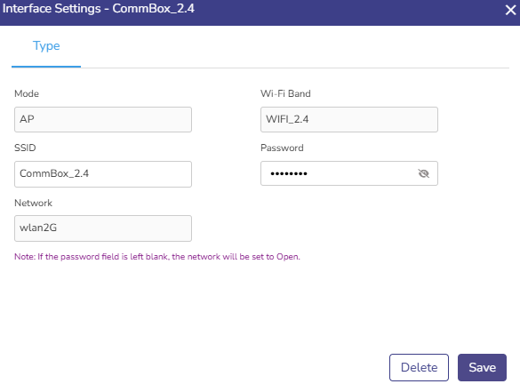
Updating a Wi-Fi Interface
To update a Wi-Fi Interface, perform the following steps:
-
Click on the Toggle icon and disable the WAN Interface.
-
Click the Gear icon next to the Interface. A popup appears.
-
Mode - Displays the operating mode of the Wi‑Fi interface. For most deployments, this remains AP (Access Point). This setting is typically not modified unless the deployment design changes.
-
Wi‑Fi Band - Shows the band on which the SSID operates:
-
2.4 GHz
-
5 GHz
-
WIFI_ALL (both bands)
-
Updating this value allows administrators to optimize coverage or performance based on client requirements.
-
-
-
Enter the SSID. This is the broadcast name of the wireless network. Updating this field changes the SSID name seen by client devices. Clients will need to reconnect using the new SSID.
-
Enter the Password. This is used to update the Wi‑Fi security key. When changed, all existing clients are disconnected and must reconnect using the new password.
-
Network - Displays the internal network (VLAN) to which the Wi‑Fi interface is mapped. Updating this value moves wireless clients to a different LAN subnet without changing the SSID itself.
-
Click Save.
-
Click on the Toggle icon and enable the Wi-Fi Interface. The Wi‑Fi interface restarts briefly to apply the updates.
All Wi-Fi interfaces, both AP mode (Wi-Fi LAN) and Client mode (Wi-Fi WAN), under a same band should use same channel and htmode, otherwise the Wi-Fi behaviour is inconsistent.
If a Wi-Fi WAN remains in the Down state for more than 5 minutes, the system automatically disables the interface.
The reason for this is a misconfigured or invalid Wi-Fi WAN (for example, incorrect settings or unsupported parameters) can cause the entire Wi-Fi band (2.4 GHz or 5 GHz) to remain unstable. This may impact other Wi-Fi interfaces operating on the same band, causing them to go down as well.
Once disabled, the Wi-Fi WAN must be manually re-enabled by the user after correcting the configuration.
Configuring a WAN Interface as Starlink
To configure a WAN Interface as Starlink, perform the following steps:
-
Click on the Toggle icon and disable the WAN Interface.
-
Click the Gear icon next to the Interface.
-
Select the WAN type as Starlink from the drop down.
-
Enter the Alias Name for the Interface.
-
Click Save.
-
Click on the Toggle icon and enable the WAN Interface.
-
The Starlink Interface is configured.
Configuring a WAN Interface as L-Band
To update a WAN Interface, perform the following steps.
-
Click on the Toggle icon and disable the WAN Interface.
-
Click the Gear icon next to the Interface. A popup appears.
-
Select the WAN type as L-Band from the drop down.
-
Enter the Alias Name for the Interface.
-
Click Save.
-
Click on the Toggle icon and enable the WAN Interface.
-
The L-Band Interface is configured.
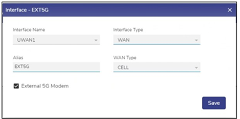
Configuring UWAN1 Interface as Ext5G
KonnectOpen System variants having Ext5G modem connected, need to be configured on the Interfaces Screen. Make sure that the Ext5G modem (Peplink 5G Adaptor) is connected to the EdgeServer uWAN1 USB3 port.
To configure the UWAN1 Interface as Ext5G, do the following steps:
-
Click on the Toggle icon and disable the UWAN1 Interface.
-
Click the Gear icon next to the Interface.
-
Select the Interface Type as WAN from the drop down.
-
Select the WAN type as CELL from the drop down.
-
Enter the Alias Name for the Interface.
-
Check the External 5G Modem checkbox.
-
Click Save.
-
Click on the Toggle icon and enable the WAN Interface.
-
The Ext5G Interface is successfully configured.
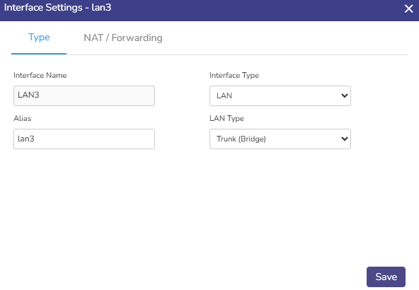
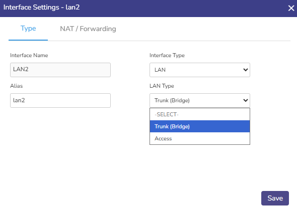
Updating a LAN Interface
To update a LAN Interface, perform the following steps:
-
Click on the Toggle icon and disable the LAN Interface.
-
Click the Gear icon next to the Interface.
-
Enter the Alias Name.
-
Select the LAN type from the drop down. If the LAN Type is ‘LAN Access’, then additionally enter the Sub I/F ID.
-
Click Save.
-
Click on the Toggle icon and enable the LAN Interface.
-
The LAN Interface is updated as required.
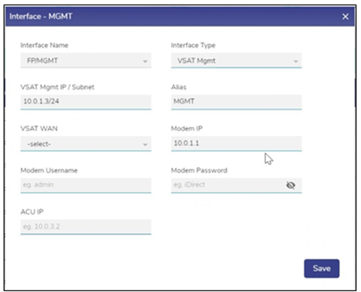
Updating a VSAT Mgmt Interface
To update a VSAT Mgmt Interface, do the following steps:
-
Click on the Toggle icon and disable the Interface.
-
Click the Gear icon next to the Interface. A popup appears.
-
Check the Interface Name.
-
Select the Interface Type as VSAT Mgmt from the dropdown menu.
-
Enter the Alias Name for the Interface.
-
In the VSAT WAN field select the corresponding VSAT interface for which this interface acts as the management interface.
-
Enter the Modem Username and Modem Password.
-
Click Save.
-
Click on the Toggle icon and enable the VSAT Mgmt Interface.
-
The Interface is updated as required.
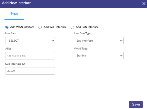
Adding a New Sub Interface
The WAN Sub Interfaces can also be called WAN \ VLAN. To add a new Sub Interface, do the following steps:
-
Click on the Add Interface button on the top right of the Interfaces screen.
-
Select the Add WAN Interface radio button to add a new WAN interface.
-
The user is prompted with add new interface dialogue box. See figure below.
-
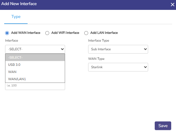
Select the parent Interface from the drop-down Menu. See figure below.
-
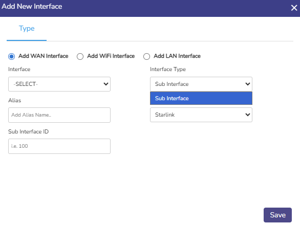
Select the Interface Type of the new Interface (WAN Sub I/F option is available) See figure below.
-
Type the Alias Name.
-
Select WAN Type of the new Interface from the drop-down menu.
-
Type the Sub Interface ID (Sub I/F ID). See figure below.
-
Click on Save.
The interface is successfully created, and the related interfaces appear together in a common color background. The original WAN Interface (WANx) under which the new Interface is created appears disabled and a new native Interface is created with the name WANx_0 (here WANx is WAN2). The new Sub Interface is disabled by default and must be enabled after creation.
-
Uncheck the All Interfaces check box to view only enabled interfaces. The new Interface creation is complete.
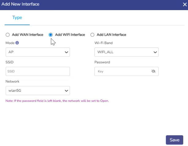
Add WiFi Interface
The Add WiFi Interface option allows you to create and configure a wireless interface for the device. This is used to broadcast wireless networks (SSID) for users to connect.
-
Select the Add WiFi Interface radio button.
-
Select the Mode. There are two options - AP (Access Point) or Client (WiFi WAN). Both workflows are explained below.
AP Mode
-
When AP (Access Point) is selected as Mode, the device broadcasts WiFi for client devices such as laptops, mobiles, and tablets to connect.
-
Select the WiFi Band for the SSID. Choose the required band depending on whether the SSID should be available on 2.4 GHz, 5 GHz, or both bands.
-
Enter the wireless network name that users will see while searching for available WiFi networks in the SSID field.
-
Enter the WiFi Password used for authentication. This password is required for users to connect securely to the wireless network. If the password field is left blank, the network will be configured as an Open Network (no password protection).
-
Select the LAN Network that this WiFi interface should be mapped to. This determines which internal LAN/VLAN network the wireless users will be connected to after joining the WiFi.
-
Click Save. The WiFi interface will be created and added to the Interfaces list.
-
The new WiFi interface becomes visible in the Interfaces table.
-
Users can connect using the configured SSID.
-
Connected devices will receive network access based on the selected mapped network.
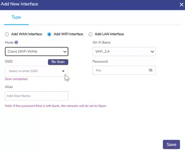
Client Mode - Setting WiFi as WAN Source
-
When Client (WiFi WAN) is selected as the Mode, the device works as a WiFi client instead of a WiFi access point. This means the device will connect to an existing external WiFi network (such as office WiFi, home broadband WiFi, hotspot, or ISP wireless network) and use that connection as its WAN (internet source). Instead of broadcasting WiFi for other users to join, the device itself joins another WiFi network.
-
Choose WiFi_2.4 (2.4 GHz) or WiFi_5 (5 GHz) to match the upstream network's band in the Wi-Fi Band field. WIFI_ALL is not available in Client mode.
-
Select or Enter SSID.
-
The system auto-scans for nearby networks when this mode is selected and populates the SSID dropdown. Use the Re-Scan button to refresh and discover available networks for the selected Wi-Fi band. Select an SSID from the list, or enter one manually.
-
SSID may only contain letters, numbers, hyphens (-), underscores (_), and dots (.).
-
-
Enter the Password of the WiFi network being joined.
-
If left blank, the system assumes the target network is an Open Network
-
-
Enter an Alias for the WiFi WAN connection.
-
Click Save.
-
The device connects to the selected external WiFi network.
-
That WiFi connection acts as a WAN uplink.
-
Internet traffic can be routed through this WiFi WAN.
-
It can also be used for WAN failover or backup internet connectivity.
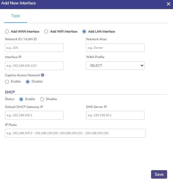
Add LAN Interface
This screen is used to create a new LAN interface and define a new internal network (VLAN) on the device. A LAN interface represents a local network segment with its own IP subnet, DHCP configuration, and access policies.
-
Select the Add LAN Interface radio button to add a new LAN interface.
-
The user is prompted with add new interface dialogue box. See figure below.
-
Enter the Network ID / VLAN ID. This value is used for traffic tagging and network isolation. Each LAN interface must have a unique VLAN ID.
-
Enter the Network Alias. This is a user-friendly name to identify the LAN network.
-
Enter the Interface IP. This specifies the IP address and subnet for the LAN interface. This IP acts as the gateway address for devices in this network.
-
Select the WAN Profile from the dropdown menu. This is an optional field to associate the LAN network with a specific WAN profile.
-
Captive Access Network - This field controls whether captive portal functionality is enabled for this LAN.
-
Click the Enable radio button to redirect users to a captive portal for authentication or access control.
-
Click the Disable radio button to allow traffic flows normally without captive enforcement.
-
-
The DHCP section controls automatic IP assignment for devices connected to this LAN.
-
Enable – The device assigns IP addresses to clients automatically.
-
Disable – IP addresses must be assigned manually on client devices.
-
-
Enter the Default DHCP Gateway IP. This specifies the default gateway provided to DHCP clients.
-
Enter the DNS Server IP provided to DHCP clients.
-
In the IP Pools field, define the range(s) of IP addresses that DHCP can assign. Multiple ranges can be specified, separated by commas.
-
Click on Save. The new LAN interface is created and appears in the Interfaces list.