
The user can configure the following three types of networks supported.
-
Connected Networks
-
Managed Connected Networks (Traditional VLANs)
-
Managed Routed Networks
Adding New Connected Network
To configure the connected network, perform the following steps.
Steps
-
Select the LAN option from the side menu bar.
-
The Access Networks tab is selected by default.
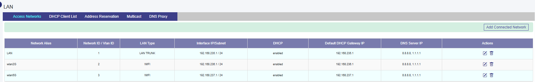
Initially, the Default network is available. The user can configure multiple networks. Once, the networks are configured, the networks become available on the Access Networks page. This section has two view, Tabular View, and Expanded View. The default view is Tabular View. Click Expanded View to see the details of the networks in expanded form, see below.
To add a Connected Access Network, perform the following steps.
Steps
-
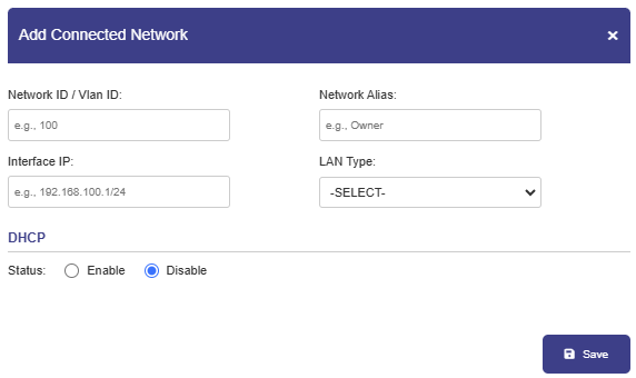
Click Add Connected Network button present on the top right of the screen. The Add Connected Network page appears, see below.
By default, Connected Networks are unmanaged, i.e., ‘Managed Connected Network?’ is set to ‘No’. See Figure Add Connected Network. To create a Managed Connected Network, set ‘Managed Connected Network?’ to Yes. See Figure Add Managed Connected Network.
Note: The user can configure multiple local networks to be used based on the hierarchy. They can configure the local network for the crew of the site, a local network for the captain of the site, and a local network for the owner of the site distinctly.
-
To enter data in the respective fields, see table below.
|
Fields |
Description |
|
Network ID |
Enter a unique numeric ID from 2 to 4090. For details about the network ID, click i icon next to the network ID. Network ID is known as a VLAN ID. Once the network ID is configured, user cannot modify or update the VLAN ID or network ID in the future. |
|
Network Alias |
Enter a unique alias of the network. |
|
Interface IP |
Enter an interface IP address and subnet mask. |
|
Managed Connected Network |
Click one of the following options.
The Managed Connected Network is the traditional VLANs’. |
|
Captive Access Network |
Captive Portal allows for each crew member/client to have a provisioned account with an associated Service Plan. The Account’s “service plan” is customized to match corporate policy (Quota, Duration, Traffic Policy – e.g., 10GB/month with defined traffic policies). Click one of the following options.
|
|
WAN Profile and Traffic Policies |
|
|
WAN Profile |
Select a WAN Profile. A single WAN Profile, I.e., Default Profile will be created in the system after the KonnectOpen System installation, and this profile will be assigned by default to any newly created Access Network. However, user can configure the distinct WAN profiles and assign to the Network. For details about configuring the WAN profiles, see section WAN Profiles. |
|
Aggregate Traffic Policy |
Select a Network Traffic Policy. A single Traffic Policy, I.e., Default Network will be created in the system after the KonnectOpen System installation, and this policy will be assigned by default to any newly created Access Network. However, user can configure the distinct policies and assign to the Network. For details about configuring the network traffic policies, see section Traffic Policies. |
|
Device Traffic Policy |
Select a Device Traffic Policy. Initially, on Network creation, no Device Traffic Policy is assigned to the network. However, user can configure the distinct device traffic policy and assign to the network. For details about configuring the device traffic policies, see section Device Traffic Policies. The user can assign the traffic policy to a device from also General Settings. For details, see General Settings. However, the traffic policy assigned to a device from this step will override the traffic policy of that device. 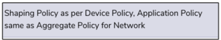
|
|
VPN |
Select a configured VPN. |
|
|
|
|
Internet Priority |
Select an Internet Priority. For details, click i next to the Internet Priority, see below. 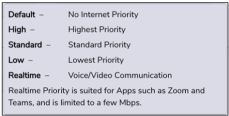
|
|
DHCP Settings |
|
|
DHCP |
To enable DHCP so that a DHCP can automatically assign the IP address and the other allied configuration details to a host on a network to communicate with the endpoints, click Enable. |
|
Default DHCP Gateway IP |
The default IP address becomes available. User can assign a new IP address. For this, click and delete the IP address and then assign a new IP address. |
|
DNS Server IP |
The default IP address becomes available. User can assign a new IP address. For this, click and delete the IP address and then assign a new IP address. They can assign a maximum of three DNS IP addresses. |
|
To configure the DNS proxy, perform the following steps. Steps
By default, the status Not In Use is displayed. |
|
|
To remove the DNS proxy, perform the following steps. Steps
Or,
The status Not in Use is displayed, see Figure Configure DNS Policy (Not in Use). |
|
|
IP Pools |
The default sequential range of the IP addresses becomes available. User can assign a new range of the sequential IP address. For this, click and delete the IP address range and then assign a new sequential range of the IP address. User can assign multiple sequential IP address range excluding the specific IP addresses of that range. This is an example. 192.168.10.2-192.168.10.100, 192.168.10.151-192.168.10.200, 192.168.10.220- 192.168.10.254 The following IP addresses will not be assigned to the device in the network.
DHCP will assign the IP address to a device on the specified network based on the IP address range. |
|
IP Reservations |
|
|
New IP Reservation |
To reserve an IP address for a device, perform the following steps. Steps
Configure the MAC Address, IP Address, Name, Traffic Policy, and Actions fields. |
|
MAC Address - Enter the MAC address of a device. |
|
|
IP Address - Enter IP address from the sequential IP address range specified in the IP Pools field. |
|
|
Name - Enter a name for the device. |
|
|
Traffic Policy - Click a traffic policy to be assigned to the device. Inherit indicates that the device will inherit the device policy of the network. |
|
|
Actions - To save the IP reservation configuration, click Green tick icon. or, To cancel the IP reservation configuration, click x. |
|
|
Bulk Upload |
To upload details of the IP reservation, perform the following steps. Steps
|
|
|
To download the bulk IP reservation template, click Download Reservations. The IP reservation template downloads in CSV format, see Figure IP Reservations Template in CSV Format. Fill in the required details in the file. For an example, see Figure Example of IP Reservations Template in CSV Format. The first row is referred to as the header row. Save the file.
|
|
|
User can modify the details of the IP reservation. To modify the details of the IP reservation, perform the following steps. Steps
Details of the IP reservation are modified. |
|
|
To delete the details of the IP reservation, perform the following steps. Steps
|
Table Connected Network Information
Modifying Network
To modify a network, perform the following steps.
Steps
-
Click pencil icon next to the network under the Action section on the Access Networks page. The Updated Connected Network page appears, see Figure Update Connected Network. To enter data in the respective fields, see Table Connected Network Information.
Note: All fields except Network ID, Interface IP, and Managed Connected Network? are editable.
-
Click Save.